Ground Truths - Use of Dynamic Cone Penetration (DCP) Testing for Foundation Design
Introduction
Dynamic Cone Penetrometers (DCPs) are popular for shallow site investigations due to their low cost, speed, and portability. This makes DCPs attractive tools for quick soil strength checks on small projects or remote sites, especially where drilling access is limited.
The use of DCP testing has been increasing within geotechnical consulting for near-surface exploration, especially in applications like road subgrades and light foundations as a rapid, low-budget alternative to more advanced in-situ testing. While engineers and project teams are often drawn to use DCP, the method’s limitations for design and potential impacts on project costs should be understood.
Based on conversations InnovoGeo has engaged with related to the use of DCP for various types of projects, this Ground Truths article is presented to further inform anyone interested in the use of DCP.
DCP Testing Method with Hand Auger Borings
In practice, a hand auger is often used to pre-bore a hole to the desired test depth, then a DCP cone is seated at the bottom of the augered hole for testing. The DCP employs a hammer dropped from a fixed height to drive the cone, and the penetration per blow is recorded at each interval. This process is repeated at successive depth increments, often by alternately augering and driving the cone.
Differences Between “US Army Corps” and “Sowers”-Types DCPs
• “US Army Corps of Engineers” - ASTM D6951 DCP: The modern “standard” DCP (ASTM D6951), sometimes referred to as a “dual mass” DCP, uses either an 8-kg (17.6-lb) or 4.6-kg (10.1-lb) drop hammer falling 575 mm (23 in.), driving a 20 mm (0.79 in.) diameter, 60° cone tip into the soil. The penetration per blow (often expressed as a DCP index or Penetration Rate PR in mm/blow) is used to estimate soil strength (commonly correlated to California Bearing Ratio (CBR) for pavements).
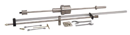
ASTM D6951 DCP. Image from Durham Geo Slope Indicator (https://durhamgeo.com/)
“Sowers” - ASTM STP 399 DCP: As described in ASTM Special Technical Publication (STP) #399 (1966), the Sowers DCP uses a lighter 15-lb (6.8-kg) hammer falling 20 in. (51 cm) onto an anvil. It drives a larger 1.5 in (38 mm) diameter, 45° cone tip, typically in a hand-augered hole, and measures blows per 1.75 in (4.5 cm) of penetration. Its blow counts (often denoted n per increment) were empirically correlated to Standard Penetration Test (SPT) N-values in certain soil types.
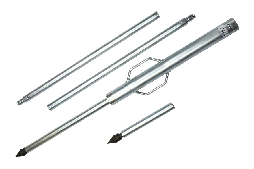
“Sowers” DCP. Image from Durham Geo Slope Indicator (https://durhamgeo.com/)
Results from the ASTM D6951 DCP and the Sowers-type DCP are not interchangeable. The differing hammer weight, drop height, and cone size mean that each device has its own range of penetration resistance values. For example, a Sowers DCP might register many more blows in a given soil than the heavier ASTM DCP, due to its lower energy per blow and larger cone area. Each device also has distinct correlation equations. Engineers must avoid mixing these results. Converting a blow count from one device to the other is not valid without proper correlation research, which is limited. While much research has been done related to the DCP, including by many state DOTs, no previous studies have found clear one-to-one correlation between DCP resistance and Cone Penetration Test (CPT) or Flat Plate Dilatometer Test (DMT) measurements, underscoring that these tools measure soil properties differently. Geotechnical reports can be found stating that DCP was performed, but not clarifying which type of DCP specifically was used.
Limitations of DCP Data for Design
Execution: Experience shows that the DCP can be used, but with significant manual effort, down to roughly 15 to 20 ft (4.6 to 6.1 m) depth in augered holes where soil conditions allow, but going much deeper becomes impractical as rod friction, hole stability, and verticality issues increase with depth. If the groundwater table is encountered, the open hand-auger hole may collapse or fill with water, often making DCP testing impossible below the water table unless temporary casing is installed. These practical constraints mean DCP testing is usually confined to relatively shallow depths and favorable soil conditions.
High Variability and Human Factors: DCP blow counts can be highly variable. Since the test is manually performed, operator technique (drop consistency, alignment, etc.) and judgment in measuring penetration can introduce scatter in the data. Even in uniform soil, successive tests might not exactly reproduce results. Dynamic effects (e.g. hammer rebound, rod connections) and soil heterogeneity (like hitting a small piece of gravel or root) can cause sudden changes in penetration per blow. For example, in some sands, dilative behavior during the impact can temporarily increase resistance, yielding unrealistic blow counts that do not reflect long-term soil strength. Conversely, in very soft or saturated zones the cone may penetrate with little resistance, but slight measurement errors could obscure these weak layers. This variability makes it risky to rely on a single DCP value for design without ample experience or statistical averages.
No Direct Measure of Soil Stiffness (Modulus): DCP blow counts primarily reflect soil strength or penetration resistance, but they do not directly yield the soil’s stiffness or compressibility. Designers must resort to empirical correlations (e.g. relating DCP index to SPT N, then N to modulus), compounding uncertainty. Research has shown poor correlation between DCP results and true stiffness parameters. This means DCP data alone are not reliable for settlement analysis. It is difficult to judge how much a shallow foundation will settle based on a DCP profile, since the test doesn’t measure elastic response the way DMT, or even CPT can.
Depth and Context Limitations: By design, DCP is a shallow penetration test. The hand-driven DCP is typically limited to a few meters depth when driving from the surface. Pushing deeper requires the hand auger method, which, as noted, becomes slow and error-prone at greater depths. Even if deeper DCP data are obtained, the effective stress increases with depth can elevate blow counts (similar to how SPT N-values rise with confining pressure), so one should apply overburden corrections to DCP in deeper holes, a practice not yet standardized – adding to uncertainty.
From STP 399: “The only inherent disadvantage is from the effects of a dynamic force on some soils. The dynamic resistance of a loose, saturated, fine-grain, cohesionless soil is likely to be lower than the static resistance; conversely, the dynamic resistance of a very dense, saturated, fine-grain, cohesionless soil is likely to be higher than the static. Therefore, the results of dynamic penetration testing must be utilized judiciously with proper engineering interpretation of the results. The indiscriminate use of any test result is fraught with danger, and this test is no exception.” Similarly, for fine-grain cohesive soils, we might expect the results of dynamic testing to be higher than those from static testing.
Comparison with CPT and DMT
Cone Penetration Testing (CPT) offers a far richer subsurface dataset than DCP. A CPT rig hydraulically pushes an instrumented cone, providing real-time, high-resolution measurements every few centimeters of penetration. Key parameters measured in CPTu include tip resistance qc, sleeve friction fs, and pore water pressure u. This continuous profile allows engineers to identify soil layer boundaries and thin lenses with precision. Moreover, CPT data is calibrated against numerous soil properties, as there are well-established correlations to soil density, friction angle, undrained shear strength, liquefaction potential, and more. Because CPT values are collected electronically and standardized, the results are consistent and repeatable. CPT provides a multi-parameter “soil fingerprint” at every depth, which is invaluable for reliable foundation design and risk assessment (something a single-index DCP cannot match).
The Flat Plate Dilatometer Test (DMT) complements CPT by measuring in-situ soil stiffness and stress with less soil disturbance. A DMT blade is advanced to depth (often using CPT rigs or drill rods) and then inflated to gauge the soil’s response. The result is a set of quantitative parameters: the material’s elastic modulus, lateral earth pressure index, and derived soil strength parameters. Unlike the purely dynamic penetration of DCP, the DMT’s controlled expansion provides a direct measure of soil compressibility. This leads to more reliable settlement predictions. Using the DMT’s modulus, shallow foundation settlement estimates tend to agree closely with actual field performance and are less conservative (more accurate) than those derived from SPT or even CPT correlations. DMT data also yield insights into soil behavior that DCP cannot, such as overconsolidation ratio (OCR) and effective friction angle.
CPT and DMT are backed by extensive research and have well-defined interpretation methodologies. Engineers can directly input CPT/DMT measurements into design methods (for example, bearing capacity or settlement) with confidence grounded in correlations developed from large databases. By contrast, the DCP provides only a single measure (penetration per blow) that must be empirically correlated to design parameters. The correlations for DCP are relatively limited, most notably to California Bearing Ratio (CBR) for pavements or site-specific SPT correlations. Beyond those, DCP lacks the broader predictive models that CPT and DMT benefit from. CPT and DMT yield richer data (continuous profiles, multiple parameters, and higher confidence in derived properties) which translates to more reliable and safer foundation designs, especially for anything beyond the most simplistic conditions.
SmartDCP and InnovoGeo’s Practice
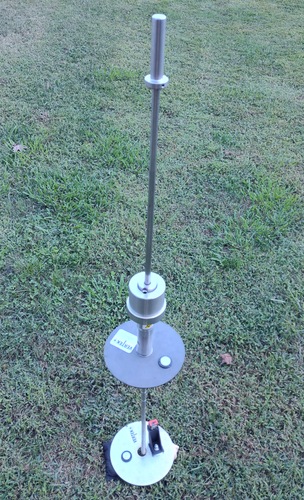
InnovoGeo Engineering utilizes the Vertek SmartDCP system, which is an ASTM D6951-compliant DCP augmented with digital tools. The SmartDCP kit consists of a standard dual mass drop hammer rod fitted with a laser distance measurement sensor and a Bluetooth-enabled system that connects to a smartphone app. With each hammer drop, the laser measures the penetration depth automatically, and the app counts blows and records depth increment data in real time. This automation eliminates the need for the operator to use a ruler and notebook after each blow, greatly improving consistency and reducing human error in the test measurements, and allows a single operator to safely and efficiently perform DCP testing. Data is instantly plotted and stored, allowing the engineer to review the penetration vs. depth curve on-site before being electronically transmitted.
The SmartDCP enables faster testing compared to the traditional manual DCP. InnovoGeo leverages this to gather shallow soil strength profiles quickly for projects like footing subgrade evaluations or pavement designs, then uploads the digital data for analysis. This enhanced reliability makes the DCP a more credible tool for preliminary design and compaction verification than it once was.
Despite these advancements, it is important to note that a SmartDCP is still a DCP at its core. The technology improves how the test is executed and reported, but it does not change the fundamental nature of the data being collected. Even with perfect technique and automation, a DCP (smart or not) provides only dynamic penetration resistance values at relatively shallow depths. It cannot measure properties like pore pressure, soil compressibility, or internal soil stresses the way CPT or DMT can. InnovoGeo recognizes this and uses the SmartDCP as one tool in our toolbox; useful for what it does, but not a substitute for more advanced tests when those are warranted. The SmartDCP’s role is often to supplement geotechnical investigations: for instance, it can fill in closely spaced test points across a site to identify soft spots, while CPTs or borings with DMT are used at critical locations. In practice, engineers must still apply judgment and, if needed, cross-verify DCP results with other data. Automation ensures DCP data is as reliable as possible, yet the interpretation of that data must still account for the device’s limitations relative to other testing methods.
Project Example
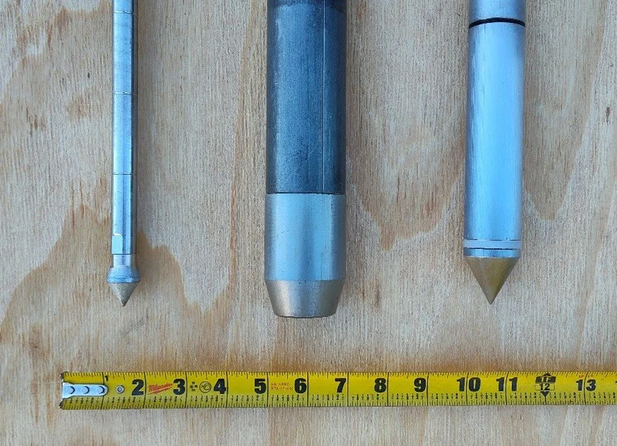
For a recent project, InnovoGeo performed several CPTu soundings for foundation design of a small structure, located within stiff Piedmont residual clay soils. To evaluate the benefit realized by this approach, a single DCP profile and two discrete SPT samples were performed adjacent to the location of one of the CPTu soundings. In the photo below, from left to right, are the DCP, SPT split-spoon sampler, and 10-cm² CPT cone used for these tests, for visual comparison.
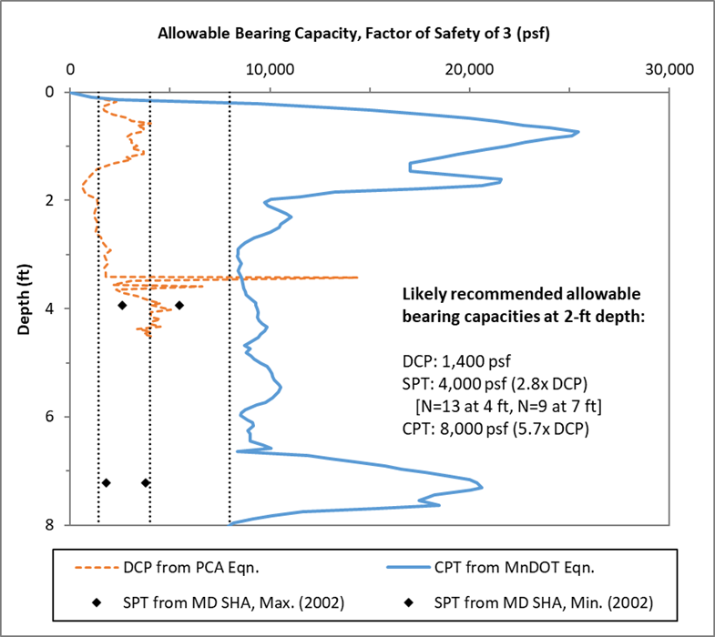
In the chart below, a graph of allowable bearing capacity with depth was prepared to compare results from the different test methods, using commonly cited correlations for each method. The spike in DCP values around 3.5-ft depth was likely due to a small rock fragment encountered in the Piedmont residual soil. The same size rock fragment may not have had as significant of an effect on the SPT or CPT results, due to the different probe/sampler diameters and energies imparted by each.
To further extend this comparison, a simple cost exercise was performed for square concrete shallow foundation (“footing”) design between the different test methods. Using the assumptions below, and several other simplifying assumptions (including lack of settlement or other checks), we can see that the use of CPT for footing design results in a percent decrease in concrete costs and concrete truck loads of 83% compared to if footings were designed based on DCP.

This simple exercise doesn’t take into account the reduction in excavated soil quantities between these scenarios, or reduction in construction schedule, but still clearly shows a significant project cost savings due to reduction in concrete required for footings.
Engineering Implications
Risk of Under-Design: Over-reliance on DCP results for design, without understanding their limits, can lead to unsafe designs. For example, if a DCP test happens to record high blow counts in a dense sand layer, an engineer might overestimate the site’s overall bearing capacity and design a footing too small – not realizing that just below that sand may lie a soft clay that the DCP didn’t clearly reveal. DCPs in silty or cemented sands can also give a false sense of security (high blows due to dilative resistance), meaning the actual soil could compress or weaken under static load more than the DCP indicated. Such scenarios could result in excessive settlement or even bearing failure (i.e. the foundation “punching” into an unexpected weak stratum).
Risk of Over-Design: On the flip side, DCP measurements can be overly conservative in certain soils, leading to over-design. A common issue is in very loose or wet sands and gravels, where the DCP may penetrate so easily (or the hole may slough) that it registers extremely low resistance, perhaps suggesting an insufficient bearing capacity. An engineer who trusts those numbers might insist on expensive ground improvement or larger foundations, when in reality the soil, in a drained static condition, could have more strength than the dynamic test implied. While it’s clear that simplified DCP results carry uncertainty, that uncertainty is difficult to quantify. If one assumes the worst-case interpretation, designs may become more costly than necessary.
Impact on Performance: The ultimate performance of a foundation (settlement, stability, etc.) is only as good as the subsurface model used in design. If that model is based on sparse or overly simplistic DCP data, the actual building or pavement may underperform. For example, unforeseen differential settlement could crack a structure if a weak layer was overlooked. Likewise, a foundation might be built far stronger (and more expensively) than needed if the soil was actually better than what the DCP indicated. In geotechnical engineering, uncertainty directly ties to risk. Using higher-quality data (CPT, DMT, and lab tests) can mitigate that uncertainty. Thus, while DCPs can guide preliminary decisions, relying on them alone for final design in anything but the most minor and lightly-loaded structures can have serious implications for safety, cost, and project reliability.
Recommendations
DCP testing should be reserved for scenarios where its risks and limitations are acceptable. It is well-suited for shallow, low-risk investigations such as checking uniform compaction of fill or evaluating the bearing capacity of a thin granular layer for a light structure. In cohesive or fine-grained soils that are near optimum moisture content (e.g. compacted clay fills or stiff residual soils), DCP blow counts tend to correlate reasonably with soil strength, making the test a useful quick check during construction. DCPs are also convenient for spot-testing many points across a site to map variability in the near-surface soil strength (e.g. identifying soft spots in a slab subgrade). They can be used during construction to verify the exposed footing subgrade, or for pavement design where correlations to CBR are applicable. DCP use should be limited to small, lightly-loaded, and low-risk structures, or where the required information is limited to a general indication of soil bearing quality, and even then, preferably in combination with some other corroborating data.
For larger or more critical projects, or whenever the ground conditions are complex, higher quality testing is recommended. CPT should be the test of choice when a continuous profile of stratigraphy and soil parameters is needed - for example, for sizable buildings or infrastructure on variable soils, or any site involving deep or soft layers, high groundwater, or seismic/liquefaction evaluation requirements. DMT is recommended when accurate settlement prediction and soil modulus information are paramount, such as for large spread footings, embankments on compressible ground, or whenever a designer wants direct estimates of soil stiffness and stress history. In general, whenever the consequence of a foundation problem is high (expensive remedial work, safety concerns) or the soil profile is not obviously uniform, utilizing CPT or DMT will generally pay off through reduced uncertainty.
If DCP testing is performed, it should be done with an understanding of its limits and ideally calibrated against other data. For example, if a site has one or two CPT or SPT borings, the results can be used as a baseline to interpret DCP blows in the same soil strata more reliably. Employ correction factors (for depth, saturation, etc.) as appropriate, and do not extrapolate DCP-based correlations beyond the conditions in which they were developed. Always maintain a healthy skepticism: if DCP results conflict with site geology or engineering intuition, seek additional data rather than forcing the numbers. By recognizing when DCP is merely providing a rough screening versus when detailed parameters are needed, engineers can avoid the pitfall of using an inexpensive tool beyond its effective or intended range. In practice, DCPs are best used as a supplement – not a replacement – to higher-quality subsurface investigation methods. Combining methods (e.g. a grid of DCPs cross-checked by a few CPT/DMT soundings) can capitalize on DCP’s coverage and CPT/DMT’s accuracy. Ultimately, designing a safe and cost-effective shallow foundation means using the right tool for the job.
However, it should be noted that several state Departments of Transportation (DOTs), including Florida, Indiana, Minnesota, and Maryland, have in recent years recommended the combined use of DCP and the Lightweight Deflectometer (LWD) for construction quality assurance (CQA) of subgrade and base materials. These paired methods are increasingly recognized for their rapid, in-situ assessment of stiffness and strength during grading and compaction operations. Some of these recent specifications directly tie LWD target moduli and deflection limits to DCP blow counts and field moisture content for both granular and fine-grained soils, while others have adopted similar procedures emphasizing comparative deflection thresholds and control strip calibrations. These protocols stress the importance of performing tests immediately after compaction and at known moisture conditions. Variability in moisture content, especially in the upper few feet of soil, can significantly influence DCP penetration resistance and LWD modulus measurements, potentially leading to inaccurate assessments of compaction quality if not carefully monitored. As a result, accurate measurement and control of moisture content are essential when applying these tools to verify subgrade performance.